Step 4 - Adding control/collision points
ClearView uses some important reference points that describe the extremes of the aircraft and which it uses to understand where the model is in three dimensional space. These take the form of coordinate objects with specific names. These are:
- COORD_NOSETIP
- COORD_TAILEND
- COORD_TAILTOP
- COORD_FLWHEEL
- COORD_FRWHEEL
- COORD_TWHEEL
- COORD_LWINGTIP
- COORD_RWINGTIP
It is important that these are placed reasonably accurately in order for ClearView to correctly orientate the model and detect crashes.

In the above picture the three wheel coordinates are being pointed out. These are in exaggerated positions for clarity. For a tail dragging plane such as this the COORD_FLWHEEL should be placed very close just underneath the left wheel and the COORD_FRWHEEL very close just underneath the right wheel. Similarly the COORD_TWHEEL is placed just under the tail wheel, tail skid or in a similar position.
For aircraft that have a nose wheel instead of being a tail dragger then COORD_TWHEEL is placed just under the nose wheel with COORD_FLWHEEL and COORD_FRWHEEL under the corresponding main undercarriage wheels.
For both types of aircraft there is a parameter that must be set later to tell ClearView if the model is a tail dragger.
Having placed the vertices for the coordinates they must be named exactly as mentioned in AC3D.
Tip: to create a single vertex point needed for the coordinates select object mode and then Line. Click in the position where the coordinate is to be placed and then right click to finish the line. This creates a line with a single coordinate which can then be moved to its required position.
Follow a similar process for the remaining coordinates.
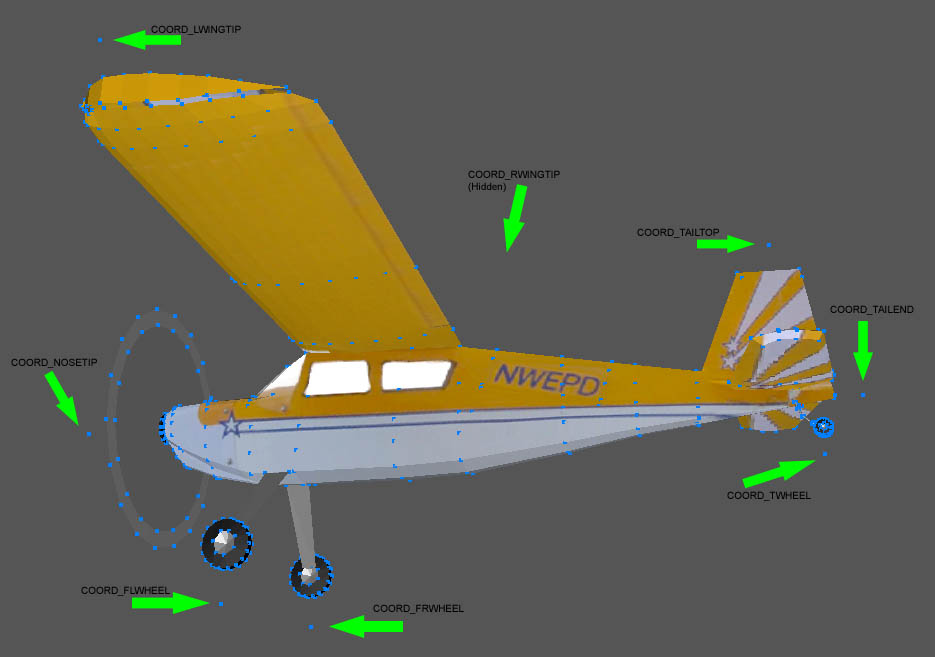
The COORD_NOSETIP would normally go just in front of the spinner or nosecone. COORD_TAILTOP is generally placed near the point that would touch to floor if you turned the plane on its back. COORD_TAILEND is generally behind the furthest back point of the aircraft. Similarly the two wingtip coordinates COORD_LWINGTIP and COORD_RWINGTIP are generally just outside of the corresponding wing tip.
The final element of model manipulation in a basic conversion is to place the model in the correct 3D space. This helps to define the centre of gravity as well as the thrust line. To ensure this is correct move the model in AC3D to align the origin (0,0,0 coordinate) at the expected centre of gravity and thrust line. This can be seen in the following picture.
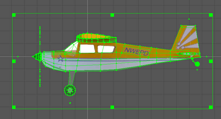
Here you can see the two axes from the front view are on the thrust line and on the wing centre of gravity.
The basic conversion is now almost complete. Whilst ClearView supports moveable propellers and control surfaces you don't need them to fly a model.
As before now is a good time to save the file.