Installation
Installing ClearView for the first time
Installing ClearView is really
simple. Download the last version from http://rcfligthsim.com
and save it where you usually save your downloaded programs. The name for the ClearView file is ClearViewSetupNNN.exe where
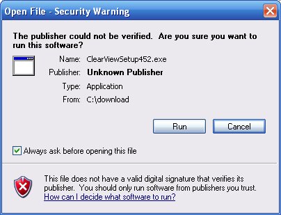
This is a normal windows security warning. Click on the Run button to start the installation. The installation starts by unpacking the ClearView installation file:
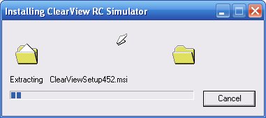
After the unpacking you will see the ClearView installation screen:
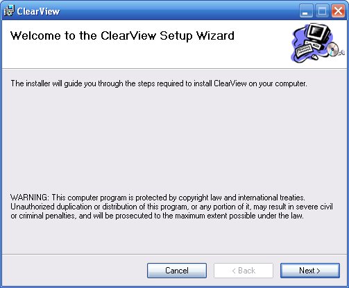
Finish the installation by following the setup wizard prompts. If you select the default installation directory, ClearView will be installed in c:\Program Files\SVKSystems\clearview You can start the program now by clicking on the ClearView icon on the desktop or selecting the program, from the program start menu.
Installing a new version
ClearView license provides free version upgrades to all registered users. New versions are frequently posted on http://rcflightsim.com together with short description what is new in the version. If you find that the new version contains feature that is important for you, you can download and install the new version. In short, you uninstall the old version, do some clean ups and then you install the new version. Please note that your license will remain “Activated”, so you do not need to do anything to transfer your license to the new version. The license is linked to your computer and not to particular ClearView version. Please follow there steps each time you install a new version:
- Uninstall the current ClearView version. Select “Start” then “Control Panel” then “Add or Remove Programs” and find ClearView. Select “Uninstall” and wait for the un-install to complete
- Delete file c:\Program Files\SVKSystems\clearview
- Install the new version as described in the chapter above.
Re-Installing your third party models
When you install a new version, all your third party models extracted in c:\Program Files\SVKSystems\clearview\models will be lost. (Remember, you MUST delete this folder: c:\Program Files\SVKSystems\clearview when upgrading to new version). Please follow these simple rules to re-install easy all your third party models:
- Have a separate models directory where you permanently store your third party models. For example, have this folder: c:\ClearViewModels\models and extract any new third party model first there. This will be the place that you never delete and can back up to keep all these models in permanent storage.
- After reinstalling ClearView, just drag and drop the models folder from c:\ClearViewModels to c:\Program Files\SVKSystems\clearview\ This will copy all your third party models under the ClearView models directory. When you start ClearView you will be able to see them all in the corresponding models menus.
Starting ClearView for first time
Start ClearView by double click on the ClearView desktop icon. You can also start the program selecting “Start” then “All Programs” then “ClearView RC”. It takes up to 30 seconds for the simulator to load the flying field and the initial model. ClearView will work on almost any Windows XP computer with specialized 3d video card. The program will also work well on many newer computers with integrated video adapters. If you have any problems starting ClearView, or if you see a black screen in 99% of the cases the reason is that you need to upgrade your video driver to the latest one. If you ever have a problem with ClearView, check what make is your video card and go to the manufacturer web site to download and install the latest video driver. To find out what video card you have, select “Start” then ‘Run” and type dxdiag After dxdiag start, select Display1 tab and read your video card model.
If the simulatior fails to run the first time, please follow this procedure:
- If the program fails or you see a black screen, download and install the latest video driver. To get the latest driver, go to your video card manifacturer web site and look for support/download links.
- If you have NVidia video card, disable the Antialiasing.
- If you can start ClearView and see the helicopter, but the program closes in one minute, go here and download and install the Creative Labs Open AL driver. If the simulator still fails when you set the sound on, please update your sound drivers.
- Some
- If you are unable to get the simulator running, send file "Program Files/SVKSystems/clearview/log.txt" to support@rcflightsim.comand we will try to help.
Setting up the controller
Supported controllers
- Keyboard
- Any Windows game pad
- SmartPropoPlus connected RC
Transmitters with PPJoy joystick driver.
Controller Options to Explore
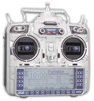
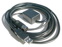
You already have RC Radio Transmitter
If you have a RC radio transmitter
that comes with "Simulator Cable", you can use it to control the
models in ClearView.
If you have RC radio transmitter, but don't have a cable, you can choose
between 3 options:
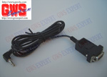
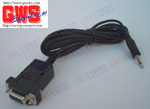
- Use a simple stereo cable to connect your Tx to the PC sound card. You will need to
download and install SmartPropoPlus interface
software together with PPJoy joystick driver. This is the most
economical option and works very well.
- Purchase
- Purchase
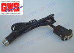
For Blade CP and Walkera transmitters, you will need a special cable
from here.
You do not have RC Radio Transmitter
This E-Sky
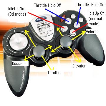
Windows game pad controllers are good solution when you are getting into RC flying. ClearView works very well with all game pads. For best results, calibrate your game pad before using the simulator. Here is a good quality Saitek gamepad that can be used:
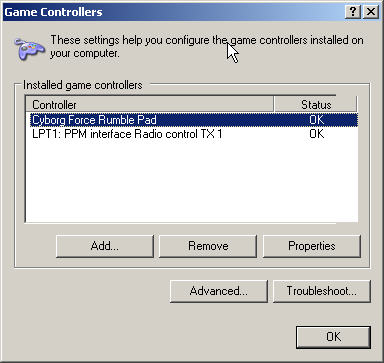
Testing and calibrating USB cable or game controller
To verify that your controller or
Setting Com parameters for PIC Serial cable
If you have
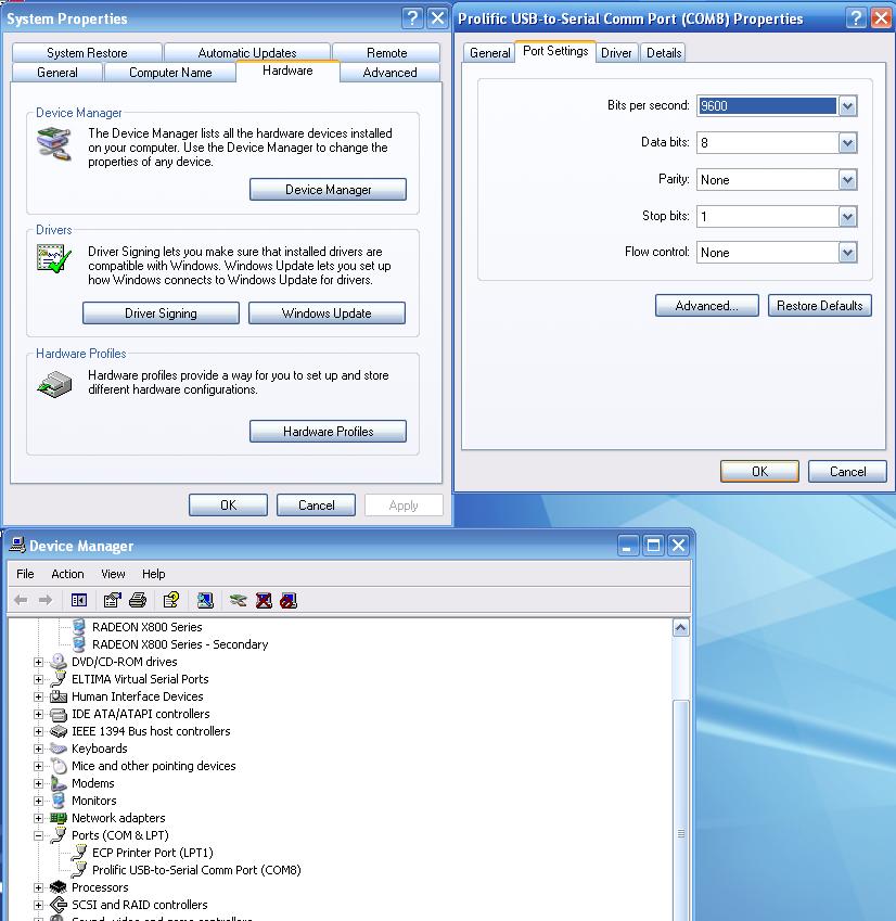
As you can see, you must select 9600 bits per second, 8 data
bits, parity none, stop bits 1 and no flow control for the cable com port. For
best results, after you set the
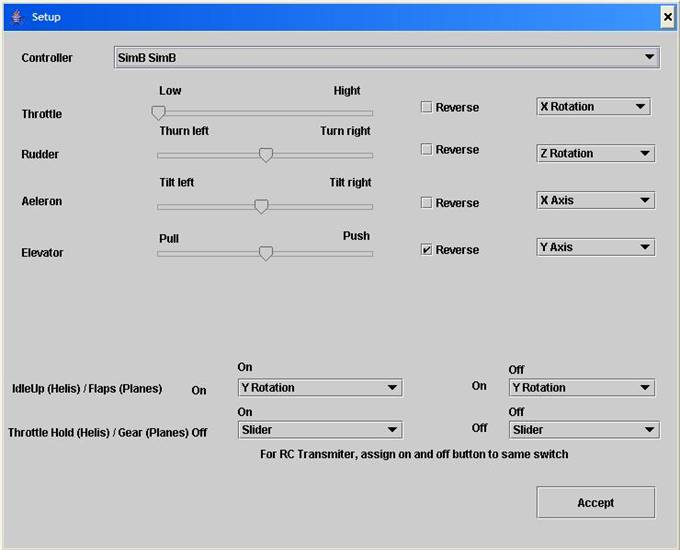
Setting Up Your Controller in ClearView
ClearView supports extensive list of controllers that you must use to control the models. By default, the keyboard keys can be used to control all model. The controllers are not recognized automatically. You must plug in your controller and have your Tx powered on before starting ClearView. Otherwise, your controller will not be recognized. After starting the simulator, you must select “Setup” then “Controllers setup” and proceed setting the controller that you want to use. Please note that you first must select the controller from a drop down list with all controllers available and then assign the specific controls to ClearView controls by using the four drop down control boxes on the right part of the controller screen.
Most of the US fliers use stick
assignment called Mode 2. In Mode 2, the left stick controls throttle and the
rudder and the right stick controls the ailerons and the elevator. After you
selected your controller from the controller drop down box, let’s start
assigning the controls. The first task is to assign the throttle control. Click
on the drop down box that is on the very left side of the throttle row. You
will see a selection of possible controls that your specific controller offers.
Your goal is to select and map the left stick back/forward control to the
throttle. Now, you have to find out,
which name represents that control. To do that, select each name one by one and
move the left stick back/forward. When you see that the throttle control bar
moves together with you moving the left stick back/forward, note the name
displayed on the throttle drop down box – this is the name for that control on
your controller. Leave that control as selected and try moving the throttle
stick again – make sure now that the control bar moves from low to high as you
advance the throttle stick by pushing it away from you. If the control bar
moves on the opposite direction, click on the reverce
check box. This will reverse the control to match the stick movement with the
control movement expected by the simulator. Repeat the same process for the
rudder, this time by moving the left stick sideways and trying to find a
control that will move the rudder control bar. The aileron and Elevator
controls are set the same way, just this time you use the right stick and
assign the back/forth control to the elevator and the left/right move of the
right stick to the aileron.
There are two special controls for
ClearView that are used for helicopters: - Idle Up
and Throtte Hold. The Idle Up control is used to
switch to so called 3d mode where the helicopter can fly inverted. When the
idle Up is on, the engine works or pre-determined power levels regarding of the
position of the throttle stick. If the idle Up is Off, the engine goes to low
rpm when the throttle is closed. The throttlehold is used to cut the engine to
idle when flying. This is used to perform auto rotations.
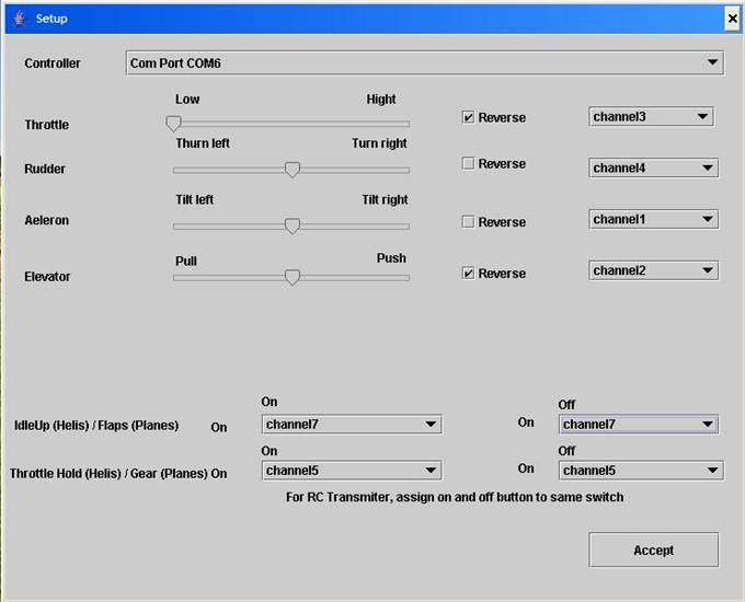
If you use RC Transmitter, you
must assign a free channel to control the throttle hold and another to control
the idle up. Typically, that channel is controlled by a flip switch on the
transmitter. In that case, you must select the same control on both drop down
boxes for idle Up, and another control on both drop down boxes for Throttle
Hold. The image bellow
represents settings for a radio Tx that
uses a
.
Here is an example setup for a serial cable connection:
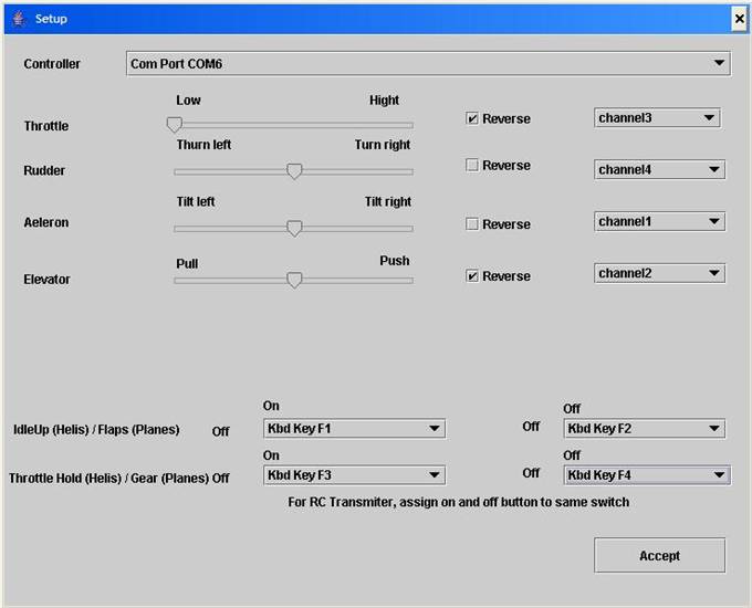
Some radios are only four
channels. You still can use them by assigning keyboard keys to Idle-Up and
Throttle Hold as shown in this sample setup screen:
You will get the best results
using your own RC radio transmitter to control the simulator. As we allready mentioned,
|
|
Picture of Milehighwings
adapter Some online stores where you can
get |
|
|
|
|
GWS |
GWS |
GWS |
Finally, please remember this: For best results, every time you press the spacebar, the
model is reset and the sticks center positions are read and then calibrated.
This allows perfect centering each and every time. Please release the
controller sticks when you press space bar to allow the center position
calibration.
If you have questions about what
cable to use, please e-mail support@rcflightsim.com
and we will help.
Common controller problems
If you have
If you see the
If you use
Some RC transmitters sold as package with electric models and with so called “sim cables” may work and some may not work or may not even be wired internally to the cable outlet. Some transmitters like Blade CP provide interface signal that has all channels mixed as CCPM and can’t be used directly in ClearView. Many people have successfully connected these transmitters using special cables from http://milehighwings.com or free cable and SmartPropo and PPJoy software drivers.
Keyboard Controls
The simulator has a default control mode that allows to use the keyboard for controlling the models. Each channel is controlled by two keyboard keys. To provide best possible control, ClearView uses innovative concept that allow smoot RC control using keys. Each channel is controller by only two keys. The channel stays always at the middle, and pressing the keys moves it from the middle more or less depending the time the key is kept pressed. The longer you press, further the control deflects. The control also deflects when you press the key fast couple times. After the key is released, the control goes back to the middle. This allows easy self centering that is equivalent to sel centering sticks – the stick always goes to the middle when released. Also, if the control is deflected, pressing the two control keys together centers the control immediately. Here are the control assignments:
Throttle: Q and W
Rudder: A and S
Aileron: Left/Right Arrows
Elevator: Up/Down Arrows
Idle Up/Down: F1 and F2
Throttle Hold: F3 and F4
F5: Zoom In
F6: Zoom Out
F9: Takes a picture from the current window
F11: Starts recording over the last selected record file
F12: Stops the flight recorder
P: Pause the simulation
SpaceBar: Resets the simulation
Activate and maintain your ClearView license
ClearView provides free trial time so you can try if the program runs well on your computer. You can purchase at any time ClearView license online at http://rcflightsim.com If you do not receive the activation e-mail in few minutes, please e-mail support@rcflightsim.com and we will make sure we help you have your program activated.
When you purchase a ClearView license, a new individual account is created for you on the ClearView web site http://rcflightsim.com. You use this account to activate ClearView and to maintain the state of your ClearView license. ClearView license is tied to your computer id. You can move the ClearView license from one computer to another using your ClearView web site account.
If you have any problems running or activating the program, if you lost your customer login id, or have any questions related to ClearView RC Simulator, please e-mail support@rcflightsim.com
Load Sceneries and models
Select “Load Scenery” and use this dialog box to load a scenery file:
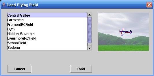
Scroll down the list if needed, then click on a row to select a scenery to load. A picture from the scenery is shown. If that is the one you want to load, click on “Load”. Be patient, since loadin a new scenery may take up to 15-20 seconds in some cases.
Select “Load Helicopter” and use this dialog box to load a new helicopter model:
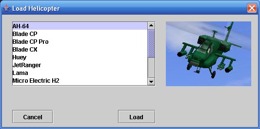
Scroll down the list if needed, then click on a row to select a helicopter to load. A picture of the model is shown. If that is the one you want to load, click on “Load”.
Select “Load Plane” and use this dialog box to load a new helicopter model:
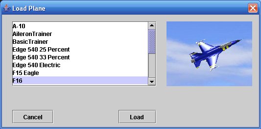
Scroll down the list if needed, then click on a row to select the model to load. A picture of the model is shown. If that is the one you want to load, click on “Load”.
Import Scenery
ClearView
implements photo-realistic flying environment using open file format that gives
you maximum flexibility to use hundreds of flying fields developed from
modelers from all over the world. ClearView is compatible and can import scenery images
created for all current RC simulators.
To import a flying field, download the jpeg file with the scenery in a
folder. Then, select “Setup” and then “Import sceneries”. You will be asked to
find the the scenery file to import. Once the file is selected, you can choose
what resolution the target scenery will be – 6, 10, 16, 24 or 32 MB. In most
cases the best choice is 16 MB – that corresponds to the typical resolution
that other simulators use. ClearView resolution can
be even higher given the input image has that extra resolution. After selecting the target resolution, ClearView will start the process of converting the scenery
into internal ClearView format. This may take up to
30 seconds. After that, the scenery is ready to use. ClearView
supports full collision detection and ClearView
sceneries can be made highly interactive by creating shadow collision objects.
Read in the next chapters how to do that.
Create Your Own Flying Site in ClearView
You can
re-create your own flying field in ClearView!
The photorealistic virtual environment in ClearView
is based on common 360x180 degree panorama format. The whole flying field is a
single digital pictures created as complete spherical (sometime called 360x180
or equirectangular) panorama. These panorama files
have aspect ratio of 2:1, corresponding to the ratio of 360 degree of
horizontal field of vew to 180 degree of vertical
field of view. As example, panorama file can have 8160 by 4080 pixels
resolution and indeed the aspect ratio is 2:1. Some other simulators use the
same panorama format, but cut the lower portion of the panorama, so the same
panorama in their format will have resolution of 8160x3060, where the bottom
1020 rows will be simply cut. The missing part is actually the view under the pilot
so it is not really important. ClearView can use both
2:1 and 8160:3060 formats. All user-developed panoramas on the Internet that
are in the 2:1 aspect ratio or in 8160x3060 size are drop in compatible with ClearView.
Using
digital camera you can take pictures from your flying site and use one of many
commercial packages to stitch You can add full collision
detection to any flying field. Just read this
document for details.
Scenery adjustments
Each scenery is represented by a folder in Landscapes folder. Fle named landscape-params.txt contains some important parameters that can be used when setting a new scenery:
groundLevel 0.0
- use distance value to adjust the perceived ground level
initModelPos -4.19 0.02 -5.224
- sets the position when
each model is loaded
initModelRot 0.0 -30.0 0.0
- set’s the initial model
orientation in space (in Euler angles)
initSpeedVect 0.0 0.0
0.0
- set’s the initial model
speed – set to non zero for hand lounched models
landscapeRot 0.0 0.0
0.0
- used to rotate the
landscape to adust for panoramas that are not
horizontally leveled.
sunLightVect 0.0 120.0 100.0
-
defines
the sun light vector for that scenery
Import FMS
Models
This function is used to import
popular
Converting
FMS models to ClearView including rotating
props, moving surfaces and landing gear
The
same manual can be used to create new models from scratch.
Import third party ClearView models
All ClearView models are exchanged on the interned as zip files. If you download ClearView model as a zip file, please follow these steps:
- Open the model file with win zip or other zip type utility
- Extract the content under c:\Program Files\SVKSystems\clearview\models
The model will be instantly available for use. It is recommended to keep all your third party models in another directory, let say c:\MyCVModels\models Extract each model you want to keep in that directory as well. If you keep all of your models there you will be able to easily copy all of then when you install a new ClearView version.
Flight Recorder
You can record and play back your flying sessions. This helps to review your flying style and eliminate common mistakes. You can also choose to show the movement of the transmitter sticks during the playback. This will help you learn how to perform 3d maneuvers when you play pre-recorded 3d session. To start a recording, select Flight Recorder and then “Record”. You will have to enter the name of the recording. To start recording, get the model ready and press function key F11. To stop the recording, press function key F12. You can share your recordings with other ClearView users. All records are saved in folder “records” under the ClearView home directory. You can e-mail any of your recordings or post them on the web. Please note, that the other party can play the recording only if they hace the same scenery and model that are used in the record.
Model Setup
ClearView implements sophisticated mathematics and very unique physics modeling engine that provide complete and full simulation for all important flight characteristics for RC model planes and helicopters. The flying qualities set ClearView apart from other simulators and that is visible in the way all ClearView models feel and fly. The flight model for each plane or a helicopter can be customized using more than 230 parameters in the Advanced Settings menu. ClearView provides the most customizable flight model from any RC simulator on the market regardless the price. The Advanced settings menu therefore is for users that are accomplished 3d pilots with ultimate knowledge what to expect from a model and willing to learn how to use all these parameters. The models provided with ClearView do not need any changes in the advanced Settings menu. The Advanced setup screen is shown bellow:
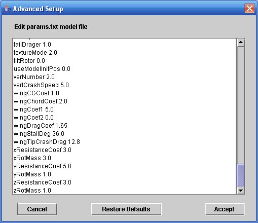
The Advanced setup can also be used to define flight model for VTOL models and coaxial helicopters.
We reccoment that Easy Model Setup is used instead, You can easy adjust the most important flying behaviors for any ClearView model using the Easy Model Setup screen.
The helicopter setup screen looks like this:
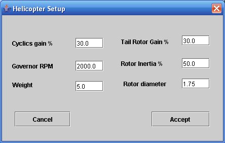
All heli models are using by
default an
After you select the proper governor
The tail rotor gain corresponds to the tail servo travel and the size of the tail blades. More gain corresponds to bigger faster tail.
The rotor inertia is used to define how fast the head speed decays in auto rotation and the capacity of the kinetic energy in the head to lift the helicopter during the final flare in autorotation.
The rotor diameter can be sued to change the rotor disk loading and is used to fine tune the feel of the ClearView helicopet to your real one.
The weight is important parameter that can significantly change the flight behavior andinertia of a model. Experiment for best results with settings close to the original value.
The Plane Setup screen looks like this:
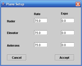
The plane setup provides ability to change the servo throws (rate) and expo setup. If you feel that stock planes are too fast for you, feel free to lower the rate as much as needed to get the desired control feel.
Plane Model Parameter Definitions
|
Parameter |
Default/Example |
Definition |
|
aelChordCoef |
10.0 |
Aileron coefficient that
amplifies the ael force. Used together with wingChord coefficient to simulate what proportion the
aileron is to the wing chord wise. If chord wise wing to aileron is
proportion 3:2, use wingChordCoef = 3n and aelChordCoef=2n where n=1,2,3.... experiment with n aelRate 100.0- used in easy setup to adjust aileron rate |
|
aelCoef |
0.2 |
Lift coefficient for the aileron
surface |
|
aelExpo |
0.0 |
Used in easy setup to adjust
aileron expo rate (-1<x<1) |
|
aelWashCoef |
1.2 |
Lift coefficient for the aileron
in the prop washstream. |
|
bodyCGCoef |
1.0 |
The same as wingCGCoef,
but for the body if you consider the plane body to be a wing. It is important
for flying knife edge and overall plane behavior when tail sliding. The
corresponding related coefficient is ruderCoef. |
|
bodyCrashDrag |
50.0 |
The drag for plane parts
touching the ground |
|
colisionRotDegCoef |
0.1 |
Use 0.1 to simulate taxing on
smooth surface, or 0.2 to 0.3 to bounce when taxing on uneven surface
0<x<lt;x<x<lt;1 |
|
dihedralCoef |
1.0 |
Coefficient describing wing
dihedral. Higher for higher dihedral. 0 to 3-4 |
|
dihedralFlag |
0.0 |
Enable dihedral flag,
0=disable,1=enable |
|
dihedralRudCoef |
1.0 |
Rudder to elevator coupling,
makes plane leans when rudder applied |
|
elevCoef |
4.0 |
Lift coef
for the elevator surface |
|
elevCompCoef |
1.0 |
Adds slight up trim so plane
flies level, higher the more up trim it is (0 to 5-6) |
|
elevCompFlag |
1.0 |
Enable elevator compensation
(0=disable, 1=enable) |
|
elevExpo |
0.0 |
Used in easy setup to adjust
elevator expo rate (-1<x<1) |
|
elevRate |
100.0 |
Used in easy setup to adjust
elevator rate |
|
elevRotInertiaCoef |
0.99 |
Damping coefficient for
stability when hovering, 0<c<=1, keep close to 1. |
|
elevWashCoef |
30.0 |
Lift coefficient for the
elevator in the prop wash stream. |
|
fieldOfView |
40.0 |
Camera field of view in degrees.
Higher number pans out, lower zooms in. |
|
frontDragCoef |
0.12 |
Front drag coefficient. Limits
the top model speed at given thrust, also slows down model when gliding and
define glide path (together with wingDragCoef) |
|
gearDrag |
20.0 |
Gear wheel drag (how fast the
model slows down when landed) |
|
gearSideDrag |
13.0 |
Gear side force (how wheels resists
sideway movements) |
|
gravity |
9.8 |
Earth gravity, use 1.5 to fly on
the moon. |
|
highWingCoef |
1.0 |
How low is the engine thrust
line under the wing, 0=thrust aligned with the wing, 1 to 3-4 the engine is
lower. Makes plane to pitch up after applying power. |
|
highWingFlag |
0.0 |
0=disable highWing
simulation, 1=enable |
|
initModelPos |
2.0 0.02 -5.0 |
Sets initial model position |
|
initModelRot |
0.0 2.5132742 0.0 |
Sets initial model rotation |
|
initSpeedVect |
0.0 0.0
0.0 |
Sets initial model speed vector
(for hand launch) |
|
landBounceCoef1 |
0.21 |
Gear bounce coefficient when
plane touches the ground under landSpeed speed, do
not set lower than this. |
|
landBounceCoef2 |
0.61 |
Gear bounce coefficient when
plane touches the ground above landSpeed speed
0<x<lt;x<x<lt;1 |
|
landSpeed |
6.0 |
Used in simulation ground
handling, use 8 for big planes 3-5 for very light and slow flying planes |
|
landXCoef |
4.0 |
Force used to simulate
landing/ground crash, tricky to set, use form similar plane |
|
landYCoef |
1.0 |
Force used to simulate
landing/ground crash, tricky to set, use form similar plane |
|
landZCoef |
1.0 |
Force used to simulate
landing/ground crash, tricky to set, use form similar plane |
|
liftConst |
3.0 |
Const that resize all surface
size. Plane with liftConst=4 has 2 times lower wing
loading than plane with liftConst=2. Note that
lower liftConst makes all flying surfaces less
effective (ailerons, elevators etc) Use together with modelMass
to get exact behavior. The modelMass will provide
mass simulation behavior like model inertia at turns, liftConst
defines how big the wing is. Note: wingDragCoef is
related to liftConst. Use wingDragCoef=
1/2 from the liftConst, or be very careful and
experiment with other values. |
|
loadRealModel |
1.0 |
Keep always to 1 |
|
maxAelerRate |
7.2 |
Max rotation rate in radians per
second that ailerons can induce. Note than 7.2 is 360 deg/sec, 14.2 is two rotation
per seconds etc. |
|
maxRolRate |
100.0 |
Max rotation rate on X axis in
radians per second |
|
maxRotRate |
100.0 |
Max rotation rate on Y in
radians per second |
|
maxScaleDist |
600.0 |
After "maxScaleDist"
meters, the program stops doubling plane in size. |
|
maxSpeed |
35.0 |
Max. prop speed for the model.
Note: that a model may not come close to the prop top speed if the body or
wing drag is high |
|
maxThrust |
700.0 |
The prop thrust in kN |
|
maxTumbleRate |
100.0 |
Max rotation rate on Z axis in
radians per second |
|
modelMass |
15.0 |
Model mass in kg |
|
modelName |
Edge540-25.ac |
The ac file name with the model |
|
modelType |
1.0 |
0=helicopter, 1=plane. Never change
this, or the program will crash. Helicopters use completely different params file. |
|
paramModelName |
PlaneParamModel.ac |
the name of the parameter model
that defines all simulated surfaces. Do not modify. |
|
pBodyCG |
-0.5 |
Body center of gravity. Negative
is moving CG forward. 0 is not necessary neutral CG. Experiment! |
|
pElev |
2.1044579 |
?? |
|
planeType |
0.0 |
0=gas, 1=electric. Electric
planes have smoke disabled and prop stops at low throttle. |
|
pRuder |
2.4273665 |
?? |
|
pWingCG |
0.9 |
Wing center of gravity. Negative
is moving CG forward. 0 is not necessary neutral CG. Experiment! |
|
ruderCoef |
4.0 |
Lift coefficient for the rudder
surface |
|
ruderExpo |
0.0 |
Used in easy setup to adjust
ruder expo rate (-1<x<1) |
|
ruderRate |
100.0 |
Used in easy setup to adjust
ruder rate |
|
ruderRotInertiaCoef |
0.99 |
Damping coefficient for
stability when hovering, 0<c<=1, keep close to 1. |
|
ruderWashCoef |
100.0 |
Lift coefficient for the rudder
in the prop wash stream. |
|
scaleDist |
300.0 |
To keep the model visible, the
program doubles the model in size every "scaleDist"
meters. |
|
slowSpeed |
8.985001 |
Define model stall speed. Used
in modeling of ground effects and glean bouncing at landing. For most models
should be 8, for very slow flying models 3-5 |
|
smokeExostPoint |
-0.1 -0.26 0.0 |
The point on the model where the
smoke originate |
|
smokeExostVect |
10.0 -4.0 0.0 |
Direction for the smoke |
|
stallCoef |
0.15 |
Uses shifting center of lift on
the wing to simulate stall wing drops, value is 0.1 to 0.5, set by
experimenting |
|
tailDrager |
1.0 |
1= tail dragger, 0= nose wheel.
Used in ground handling. Plane must have properly named wheels. |
|
textureMode |
2.0 |
Use 2, can be integer from 0 to
40, too hard to explain |
|
tRolCoef |
4.0 |
Torque Roll Coeficient |
|
tRolFlag |
1.0 |
Enable torque rolling |
|
tRolSpeedLimit |
5.0 |
|
|
useModelInitPos |
0.0 |
If set to 1, will set init model
position from initModelPos and initModelRot
if set to 0, will set init model position from landscape params
file. |
|
vertCrashSpeed |
4.0 |
defines vertical speed above
which touching the ground will result in crash. |
|
wingCGCoef |
1.0 |
Goes together with elevCoef. Higher elevCoef+lower
wingCGCoef = Lower evelCoef
+ higherwingCGCoef for elevator agility. If you
want the plane to snap fast when doing tail slides, go with Lower evelCoef + higherwingCGCoef, if
you want plane to tail slide quite a bit, go with Higher elevCoef+lower
wingCGCoef |
|
wingChordCoef |
10.0 |
Drag coefficient for induced
drag when the wing rotates during roll |
|
wingDragCoef |
1.1 |
The drag for the wing. Set it to
liftConst/2 for start, then experiment. For example, gliders have low wing
drag, biplanes high |
|
wingStallDeg |
35.0 |
The stall degree for the wing.
Some Delta Wings may have stall deg. up to 90 deg. For aerobatic planes use
20-45, or if you want expressed wing stall, use 12-13. |
|
wingTipCrashDrag |
20.0 |
The drag if wingtip touches the
ground |
|
xResistanceCoef |
3.0 |
|
|
xRotMass |
3.0 |
Model mass distribution along x
axis, affects aileron response and ground handling |
|
yResistanceCoef |
5.0 |
|
|
yRotMass |
1.0 |
Model mass distribution along y
axis, affects rudder response and ground handling |
|
zResistanceCoef |
3.0 |
|
|
zRotMass |
1.0 |
Model mass distribution along z
axis, affects elevator response and ground handling |
The table is courtesy to Gregory Matthews and Kennet Green.
Camera and Zoom Setup
ClearView provides 3 camera model and 3 zoom modes that helps in maintaining best possible view for the model while keeping the ground in sight. The camera views are “Direct”, “AI” and “Dynamic”. To select the proper camera view, select “Settings” then “Camera Setup”. You will see a screen like this:
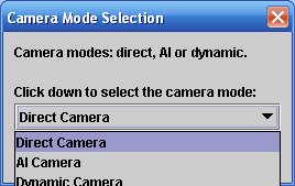
Clicking on the drop down box will allow you to select the desired camera mode. The direct camera view keeps the model in the center of the screen and simulates you following the model by rotating your head so the model is always in the center of your vision. This is useful simulation for the way beginner RC pilot follows the model very close and is “blind” for anything what happens on the side. The dynamic camera mode simulate how most advanced pilots follow the model – they face the general direction of the model, but follow the model with eye movements. The camera simulates both movements and provides immersive environment that feels real. The AI camera model stand for “Artificial Intelligence” and uses “fuzzy logic” trying to anticipate the future model movements while trying to represent as much of the ground while still keeping the model on screen. The simulator for example, will know that the helicopter is high in the sky and makes autorotation. The camera will be gradually positioned so the helicopter is show slowly at the top of the screen so the there is enough time for you to react and see the ground when the ground shows up.
There are 4 different zoom modes: 25 degrres, 39 degrees, 50 degrees and “Custom”.
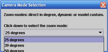
The first 3 zoom modes provide fixed field of view. The 50 degree provides wide view of the field and is usefull for wide monitors to create real cinematic experience. The 25 degree can be used with smaller models so you don’t loose them from site. The 39 degree is the natural field of view and provides a good balance between the need to have general field awareness and good view of the model as well. The “Custom” view mode (not shown on that picture) provides the most flexible way to control the zoom model. The “Custom” view mode is controlled for each model based on 3 parameters in the model params.txt file. These parameters can be edited in the advanced model setup. This allows you to define a “Custom” zoom behavior per model that allows you to see that model best. The parametsrs that control the custom zoom are:
fieldOfViewNear defines the field of view
(zoom) when the model is on distance lower than startZoomDistance
fieldOfViewFar defines the field of view
(zoom) when the model is on distance bigger than endZoomDistance
When the model is on
distance between fieldOfViewNear and fieldOfViewFar, the zoom changes slowly and proportionally
from fieldOfViewNear to fieldOfViewFar
Let’s see how the zoom will
change if the parameters are set as follows:
startZoomDistance 30.0
endZoomDistance 100.0
fieldOfViewFar 20.0
fieldOfViewNear 50.0
If the model is closer than
30 meters, the zoom will be wide, at 50 degree field of view. As the model
flies away, between 30 and 100 meters, the camera will gradually zoom from wide
view (50 degree FOV) to zooming at the model up to 20 degree FOV when the model
arrives at 100 meters distance. This will let you see the model and the scenery
quite well. After the model continuies to move
further away, after the 100 meters distance, the zoom will stay constant at 20
degree FOV so you don’t get false feeling that the model is not moving away.
Smoke and sound setup
ClearView provides fully 3d sound. The sound engine is driven by the model position and uses Doppler effects that provides the most realistic stereo sound available in RC simulator. The sound is controlled by the “Settings” menu and can be turned off if you preffer to play music when flying. The smoke provides those extra visual clues that helps us when we flyin the real model. If you have slower frame rates you may turn the smoke off from the “Settings” menu.
Servo Setup
You can select and assign different servo sets to any ClearView model. In addition to the full flight simulation, ClearView simulates number of popular RC servo types with different speed, resolution and centering precision. Use this screen to select and assign a new servo set to the current model:
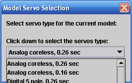
Once assigned, the servo sets are kept with the model, so the next time you load the same model, the servo set that you selected for that model last time is still current.
Training and Magic Time scale setup
Slowing down the time is the best way to learn to fly RC models. To get to the magic time setup, select “Settings” and then “Magic Time Scale”. You will see screen like this:

If you select value of 100, the time flows “real time”. Any value under 100 slows the time, for example if you enter 50, time will flow two times slower than normal. You can speed up the time up to 1.5 times the normal time by entering a number between 100 and 150. Usually you spoeed up the time when you want to train is conditions harder than in real flight so you are better prepared if you get into challenging situation.
Weather Setup
Use the following screen to create different weather conditions:
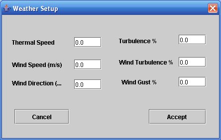
The speed is always in meters per second. The wind direction is in degrees from 0 to 360 and the rest of the parameters are percents between 0 and 100.
The Thermal speed defines the Up/Down speed of the ear mass over the flying field. If you select Thermal speed 1 that would mean that there will be updraft of 1 ms which is 3.6 km/hour or 2 miles per hour updraft speed. The Turbulence parameter defines how often and now much the thermal speed goes lower than the thermal speed. For example, if you select Turbulence 100% that will means that at certain moments the thermal speed will be varying from 0 to 1 m/s. If the turbulence is 50% the termal speed will vary from 0.5 to 1 m/s.
The Wind speed defines the speed of wind in m/s. The wind turbulence defines how low the wind speed drops from the value set in Wind Speed parameter.
The Wind Gust parameter defines how often and wind gust occurs and what is the intencity curve of the wind gust front end.
Since you can’t feel the wind with your body in similar way when you are flying at the real field, use lower wind sped values to create more challenging environment to fly. If you select to high values, the models can become very hard to fly.
Fly together over the Internet - multi-player setup
ClearView provides ability for
two players to set a network session and fly together. Each user flies his own
model, but is able to see and hear the model flown by the other party. This
unique capability of ClearView will let you fly
together with a friend the same way you fly with other people in your local
club. Keep in mind, that the camera will follow your model. You will see the
other model only when it comes in the camera field of view. ClearView
provides full stereo sound with complete spatial information so it is easy to
guess where the other model is when you do not see it. It is good practice to
keep the models close - either try to fly formation when flying planes, or
hover in close proximity when flying helicopters.
Setting up peer to peer networking requires
some level of understanding how to enable your host and port for peer to peer
networking. Most of the residential computers are behing
router and a firewall. Make sure you understand all what you are doing. There
are a lot of resources on the net, or just ask a friend for help. Going to a
simulator user group like this
can be a lifesaver. Just ask for help on setting multiplay
for ClearView.
ClearView comes with the
network multi-play disabled. The reason is, that your computer ports are
guarded by security programs that you may have installed to keep your computer
from viruses and other threats. You must manually enable the ClearView multi-play and configure your security programs
and firewalls are to allow network play. To configure ClearView
for net play, you must edit startupParams.txt (Under Program Files/SVKSystems/clearview folder) and change some lines.
Here are the lines that control ClearView net play:
myHost localhost
myPort 0
netHost1 localhost
netPort1 0
When ClearView
starts and see that myPort is 0 and netPort is 0, ClearView will have
the net play disabled. ClearView will work in the
usual in local mode. This is the normal way you want to use ClearView.
Even after a net play session, you must go back and edit this file and change
the ports to 0. This will allow ClearView runs in
local mode when started next time. Let's now review the parameters one by one.
myHost must allways be localhost.
For network play, you must select a number for
myPort parameter. We suggest to use 31000. Your
friend can also select the same number, let say 31000 as well.
Now, you need to find what is
your computer
Your host is: 122.22.2.200
You choose port number 31000
Your friend host is: 133.33.3.300
He chose port number 31000
In your startupParams.txt , your lines must be
completed like that:
myHost localhost
myPort 31000
netHost1 133.33.3.300
netPort1 31000
Your friends startupParams.txt lines must be
completed like that:
myHost localhost
myPort 31000
netHost1 122.22.2.200
netPort1 31000
Save the newly configured startupParams.txt .
Your friend must also save his startupParams.txt Congratulations, you just
completed the network setup for ClearView net play!
Now, you have to enable your computer to work
as peer to peer over the internet. Let's assume that you know how to do that
and you both allready have your computers enabled.
After you and your friend enabled your
computers for net play, you must check if that is really the case. Go to this
url to test if your
computer address is internet accessible. On the page you wil
see your computer
Ok now, we are getting close. Now, you tested
that your computer pungs fine, and your friend tested
on the same page that his computer pings fine.
The last step is to make sure the port is
punched tru (it is enabled). To do that, start ClearView and do to this page. On the port scan line, in
the custom field type your port number (in our example it was 31000) and click
go. If you get this message:
The host 24.6.43.60 does not have a service
running on port 30000 ().
than means you have to map the local computer
port to the router and expose that port on the internet (nice, now you can get
that router manual and read it again...).
If you get: The host 24.6.43.60 have a service
running on port 30000 ().
you are all set. Another ClearView
instance from the net will be able to connect to your ClearView
program for mulit-play.
Your friend must start ClearView
and both programs will connect automatically. If for some reasons he does not
see your model, he must perform the port test from his computer to make sure
his port is exposed for communication.