Create collision objects in ClearView
RC sceneries
Introduction
ClearView uses photorealistic flying field created from real
flying fields. To provide even better simulation, ClearView
now provides real collision detection with objects from the scenery. This
document describes how to add collision objects to an existing photo field.
Each scenery is represented with a directory under landscapes. In
this directory, a file named landscape-params.txt defines some important
settings for that scenery, like the initial model position, the weather
parameters etc. There are some parameters that will be described here:
loadObjects
If loadObjects
is 1, data/objects.ac will be loaded. This allows adding
extra 3d to the photo scenery. This is used to add houses, trees, runways and
helipads that do not exist in the actual photorealistic scenery.
textureMode
If set to 0, the texture does not assume the material
attribute from objects.ac The
objects appear flat. If set to 2, the texture is combined with the material
attributes from objects.as the same way this is done
when texturing models.
loadSkyBox
If loadSkyBox
is 1, the photo realistic scenery is loaded. If 0 the scenery is not loaded. In
that case you must set loadObjects 1 so at all 3d
objects from data/objects.ac are loaded. This is used
for pure 3d sceneries.
loadCtlObjects
If set to 1, all 3d objects
from data/controls.ac will be loaded and used for
collision detection. If set to 0, collision detection will be disabled. As a
first step in creating collision detection for a scenery and empty controls.ac must be created with ac3d from ac3d.org and loadStlObjects must be set to 1.
The collision detection
works when loadCtlObjects is set to 1. In that case,
all objects from ctlobjects.ac are loaded and kept
invisible. The model movement is tracked and any time the model body intersects
with any of the collision objects the simulator will simulate crash of the
model. That way the pilot can learn to keep away from different obstructions.
Creating collision file
The key into creating proper
collision effects is creating of background collision objects that stay exactly
where real artifact or objects are shown on the photo field.
Here are the steps that must
be followed in creating collision object file controls.ac:
Enter “Collision Design”
mode. To get into that mode, load any helicopter model and select “Advanced
settings”. Change the value for specialMode parameter from 0 to 1 or 2 and save the
settings. This will let you control the helicopter in special easy way so you
explore the photo scenery and match the hidden collision objects to the current
scenery. Use the sticks to move the model. Idle Up is used to reload and show
the current collision objects and Throttle hold is used to set the coordinate display
on/off. You must set the coordinate display off in order to use the menus.
For each object on the photo
field, move the CM model to all corner vertices points of the object and write
down the vertices coordinates.
Create the object in ac3d
using the vertices coordinates obtained from the step above and save the result
in controls.ac
Load controls.ac
and check if the object is placed in the proper place
Switch IdleUp
on/off to show on/off the newly created object and make sure it really lies
right where the real object from the photo field is.
Move the model and observe
if the collision is indicated when the model collides with the object.
Go to the next object and
repeat the same process until done with all objects.
The model shape from the model
3d object is used for the collision computations. To have different shape (or
include the main rotor) create file colbody.ac with
the proper model shape that will be tested for collision. It is desirable,
instead the model shape from the model ac file, to create simpler shape in colbody.ac file. This will increase the performance.
Collision design mode commands
ClearView is placed in collision by going into Collision
design mode. To get into that mode, load any helicopter model and select
“Advanced settings”. Change the value for specialMode parameter from 0 to
1 or 2 and save the settings. To exit
from that mode, change the specialMode settings back to 0 or load any other model.
UdleUp
– When on, loads and shows
the current content of controls.ac. When off, clears
all controls.ac objects from the screen.
ThrottleHold – When on,
shows a message with collision indicator, exact model coordinates and distance.
If set on, the menus are inaccessible. Set the switch to off to clear the
message and makes all menus accessible again.
Throttle stick – moves CM
model up and down around the Y axis.
Elevator stick – moves CM
forward and back along the Z axis.
Aileron stick – moves CM
model forward and back along the X axis.
Following is step by step instruction for collision
enabling FarmField
FarmField contains a fence on the right side of the model
start area. I will document step by step how to add collision for that fence.
Adding more collision objects is basically repeating that same process again.
First, I entered into
collision design mode as described above.
I use my own helicopter model that is represented by football ball and a
donut but you can use any helicopter you like, just change specialMode
parameter to 1 or 2 (for two different stick modes of movement).
I expanded the file under
model directory and started ClearView. I loaded FarmField and then loaded CoordSelector
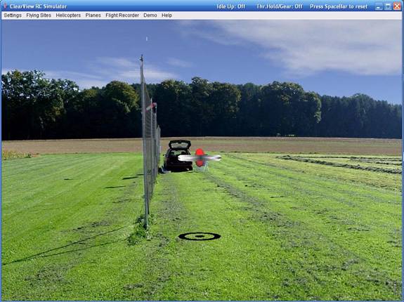
model. The program changed into collision design mode:
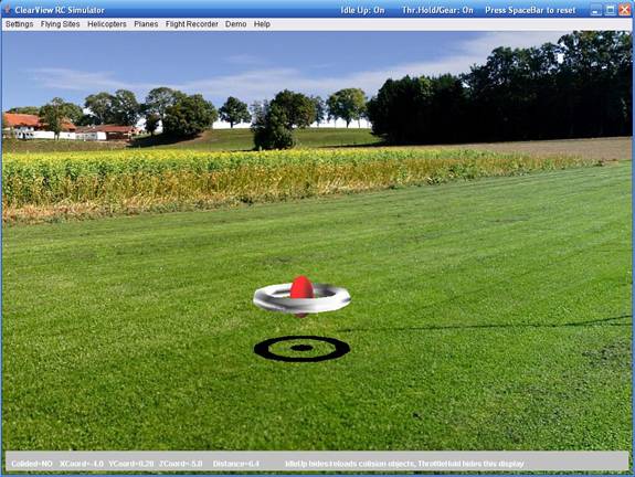
Note the message bar at the bottom. You can
toggle it on and off via Throttle Hold switch. Note that when the bar is on,
you can’t select the menus, so switch it off when need to select something from
there.
The center of the red ball
is the current model coordinates. The center of the black dot at the shade is
the vertical projection of that coordinate on the ground (X,Z).
You can move the model with the sticks and write down any coordinates that you
may need to create the collision objects.
Now, I am going to take the
coordinates of the net so I can create a proper collision object for it. Let’s
move the model to the first point I want to take:
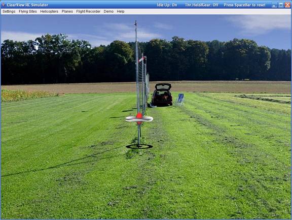
I want to take the
coordinate at the base of the net. I lifted the model and position it so the
shade gets exactly at the base of the net. Now I am ready to lower the model exactly
at the desired place:
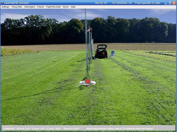
Now the center of the model
is positioned exactly at the point that is the base of the net. Now I can write
down that point coordinates as shown on the message bar:
Net base point:
(-0.01,-0.23,-10.62)
Now I move the model up and
little to the left at the top net point:
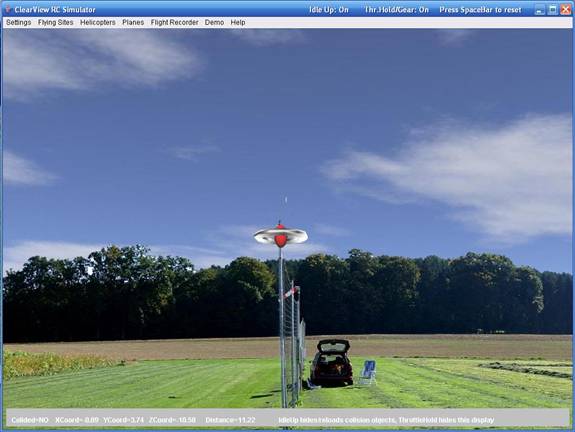
Net top point: (-0.09,3.74,-10.58)
Not I want to get the net
bottom point at the end of the net far at distance:
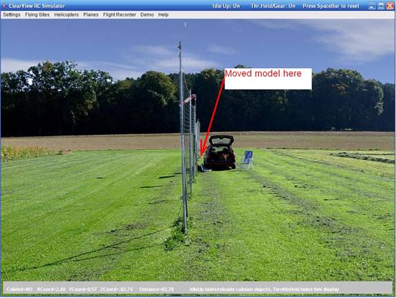
Net base point back: (2.48,0.57,-82.74) Moving the model up I get the net base point top:
(2.39,6.26,-82.74)
I ended up with four points:
Net base point:
(-0.01,-0.23,-10.62)
Net top point: (-0.09,3.74,-10.58)
Net base point back: (2.48,0.57,-82.74)
Net top point back (2.39,6.26,-82.74)
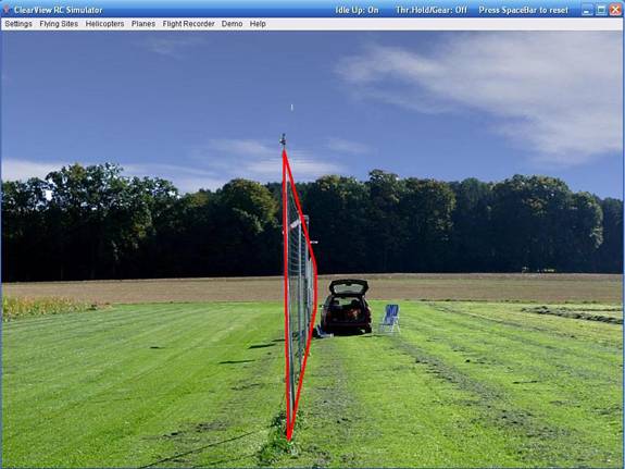
Here is the four point
surface I defined:
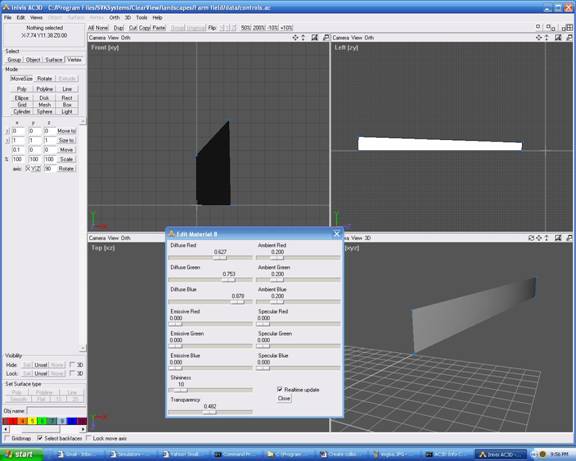
Now let’s fire ac3d . Create a
rectangle and then drag each of its vertices to exact coordinates that we
extracted for the net in the step above. Then apply a material and set the
transparency to 50%. Then save the file as controls.ac
in data sub directory of the Farm Field. Here is a screen from ac3d:
Keep ac3d open. Now we will
load this in ClearView and see how well this covers
the mesh. If needed, the object can be moved in ac3d and saved. On ClearView, by flipping the Idle Up switch the new changes
will be loaded so we try again for match. That process can continue for some
iteration for more complex models.
Here we see the collision
object and the net. Flip few times the Idle Up switch. This hides the collision
object and reloads all collision objects from controls.ac
We see that the top of the object does not align with
the top of the net. Let’s move the top vertex in ac3d, save in ac3d and reload
flipping the idle up switch.
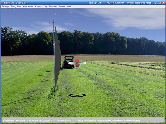
Here is the finished image
from ClearView with the collision object shown over
the net:
We can repeat the same
process for the car or any other objects that we may want to make collidable.
To verify that the collision
object for the new is working, load any model and try to hit the net.